Within Sky Detectors
Why Every UAP Sensor Needs the Same Clock
Accurate clocks let analysts compare sensors, stations, aircraft data, and environmental readings without guessing the order.
On this page
- Why timestamps are evidence
- GPS timing and network clocks
- What timing errors do to reconstruction
Page outline Jump by section
Introduction
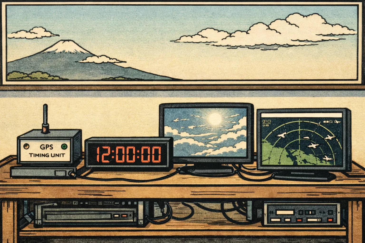
Accurate timing is one of the least glamorous parts of automated instrumented UFO detection, but it is also one of the most important. A video frame without a trustworthy timestamp is only a picture; a video frame with a known clock, known uncertainty and matching sensor records can become evidence. In UAP work, the clock is what lets analysts compare a camera track with radar returns, ADS-B aircraft messages, weather readings, satellite overpasses, acoustic sensors and observations from a second station.
This matters because many striking sky events are brief, fast and ambiguous. NASA’s 2023 UAP study found that current analysis is hampered by poor calibration, missing metadata, lack of multiple measurements and lack of baseline data; it specifically identifies time, location and observing modes as part of the metadata needed to interpret a recorded event. [NASA Science]science.nasa.govNASA Science… In automated detectors, “what happened?” often depends on a quieter question: “did these measurements happen at the same moment?”
Why timestamps are evidence
A timestamp does more than sort files into chronological order. In an instrumented UAP record, it is part of the measurement. It tells the analyst when a sensor saw a light, when a pan-tilt unit moved, when an aircraft transponder packet was received, when the wind changed, when a microphone heard a pulse, and whether two geographically separated stations were observing the same thing or two unrelated things.
That is why time belongs with calibration and provenance, not with office administration. NASA’s UAP report argues that AI and machine-learning tools only work on well-characterised data gathered to strong standards, and that future UAP analysis needs multiple, calibrated sensors with thorough metadata rather than isolated clips. [NASA Science]science.nasa.govNASA Science… The Galileo Project makes the same point through its observatory concept: wide-field cameras, narrow-field instruments, passive radar-style receivers, radio spectrum monitors, microphones and environmental sensors are useful because their measurements can be fused, cross-checked and used to reject artefacts. [Galileo Project]galileo.hsites.harvard.eduGalileo ProjectThe Scientific Investigation of Unidentified Aerial Phenomena (UAP) Using Multimodal Ground-Based Observatories | The Gali… Without common timing, that “multi-sensor” record can degrade into several separate anecdotes.
Timing also changes what counts as corroboration. Two cameras showing a bright object are not automatically two observations of the same object. To compare them, analysts need to know whether the frames overlap in time closely enough for the object’s apparent direction, angular speed and brightness to be physically compatible. A one-second error may be harmless for a slow cloud illumination, but it can be decisive for a meteor, a nearby bird, a drone crossing a wide field, or a satellite flare that appears and fades quickly.

The same clock makes multiple sensors comparable
Automated UAP stations are usually built around heterogenous instruments: cameras may run at 25, 30, 60 or more frames per second; radio receivers may log events continuously; environmental sensors may sample every few seconds; microphones may record at audio rates; pan-tilt mounts may report positions after internal processing delays. Clock synchronisation is the mechanism that turns these different streams into a shared event record.
The Galileo Project’s published observatory architecture is a useful concrete anchor. Its 2025 Observatory Class Integrated Computing Platform is designed to collect multimodal data from multiple sensors, manage provenance, support real-time acquisition, and later analyse events through commissioning, census operations and science operations. [arXiv]arxiv.orgar Xiv11 Introduction… In that kind of system, clock discipline is not a decorative feature. It is what allows a post-processing pipeline to ask whether an optical track, an acoustic signal and a radio-frequency feature belong to the same event window.
The same logic is visible outside UAP research. The OpenSky Network, a large ADS-B aircraft sensor network used for aviation research, records raw aircraft messages at sensor nodes with nanosecond-precision timestamps for time-critical evaluations that require tight synchronisation. [opensky-network.org]opensky-network.orgA Large-scale ADS-B Sensor Network for ResearchFebruary 9, 2014 — by M Schäfer · Cited by 761 — OpenSky records all messages as they are received by sensor nodes, including nanosecond… Meteor-camera networks also show why this matters: one recent multi-station meteor monitoring design highlights built-in GPS timing to about one microsecond as a key feature for accurately timing atmospheric entry. [arXiv]arxiv.orgOpen source on arxiv.org. UAP detectors face similar reconstruction problems, even when the target ultimately proves to be ordinary.
GPS timing and network clocks
Most practical UAP detector designs have three broad timing choices: use a satellite-disciplined clock at the station, synchronise computers over a network, or combine both.
A GPS or broader GNSS receiver can provide a pulse-per-second timing signal and a UTC time reference. In scientific and engineering systems, this is often used to discipline a local oscillator so that timestamps remain stable even when the computer operating system is busy or the network is variable. A NASA technical paper on using GPS receiver one-pulse-per-second output illustrates the basic principle: the pulse is treated as a timing reference against which recorded data can be aligned. [NASA Technical Reports Server]ntrs.nasa.govTechnical Reports Server USING GPS RECEIVER 1PPS OUTPUT TO VERIFY TIMETechnical Reports Server USING GPS RECEIVER 1PPS OUTPUT TO VERIFY TIME Physics experiments use the same idea at higher precision; a GPS-based timestamp facility at Gran Sasso National Laboratory was designed to assign accurate timestamps to underground detector events and reported 15 ns one-sigma timing accuracy. [arXiv]arxiv.orgarXiv Accurate GPS-based timestamp facility for Gran Sasso National LaboratoryarXiv Accurate GPS-based timestamp facility for Gran Sasso National Laboratory
Network Time Protocol, or NTP, is the common, low-cost way to keep computers roughly aligned to UTC over packet networks. It is good enough for many administrative and monitoring tasks, and the original NTP literature describes long-term accuracies on the order of a few milliseconds under suitable conditions. [NTP: Network Time Protocol]ntp.orgOpen source on ntp.org. But NTP accuracy depends strongly on network latency, asymmetry, operating-system scheduling and configuration. For UAP reconstruction, that means NTP may be adequate for slow event correlation, but it should not be treated as automatically precise enough for frame-level or time-of-arrival analysis.
Precision Time Protocol, or PTP, is designed for more demanding local networks. The IEEE 1588-2019 standard describes a protocol for synchronising clocks with sub-microsecond accuracy and precision using modest network and computing resources. [IEEE Xplore]ieeexplore.ieee.orgOpen source on ieee.org. In an observatory setting, PTP can be especially useful when several sensors feed one local edge-computing system, because it can align cameras, receivers and acquisition boards more tightly than ordinary internet timekeeping.
The practical distinction is simple: GPS or GNSS gives a station a strong reference to world time; PTP can distribute precise time inside the station; NTP is often acceptable for coarse logging and system administration but risky as the only timing foundation for high-speed reconstruction.
What timing errors do to reconstruction
Timing errors do not merely add a little fuzz to a UAP record. They can create false speed, false acceleration, false coincidence and false mystery.
The clearest failure mode is triangulation. If two cameras at known locations observe an object, analysts can estimate its three-dimensional position only if they know where each camera was pointing and when each image was taken. The Galileo Project’s observatory paper explicitly links wide-field cameras to deriving object positions and kinematics using triangulation. [Galileo Project]galileo.hsites.harvard.eduGalileo ProjectThe Scientific Investigation of Unidentified Aerial Phenomena (UAP) Using Multimodal Ground-Based Observatories | The Gali… If one station’s clock is late by half a second, a moving aircraft, drone, meteor or nearby insect can be paired with the wrong point in the other station’s video. The resulting 3D track may look physically strange even though the input observations were ordinary.
A second failure mode is bad velocity. Suppose a detector records an object crossing ten degrees of sky in two seconds, but the frame timestamps are actually delayed or irregular because of buffering. The angular speed estimate changes immediately. If the distance is then inferred from triangulation or assumed from aircraft altitude, the speed estimate can shift from mundane to implausible. NASA’s UAP report warns that evidence thresholds are needed to avoid errors with automated methods, and says purpose-built sensors should be able to adjust on millisecond timescales while alert systems share transient information quickly and uniformly. [NASA Science]science.nasa.govNASA Science… Millisecond-scale system behaviour is hard to interpret if the event record itself does not preserve millisecond-scale timing honestly.
A third failure mode is false coincidence. A magnetometer spike, microphone transient, aircraft ADS-B packet or weather change may look related to a visual sighting if the event window is too wide or the clocks drift. Conversely, real coincidences can be missed if sensors use different clocks and no uncertainty is recorded. In a serious event file, a timestamp should therefore be accompanied by an uncertainty estimate: for example, “frame exposure midpoint known to within 2 ms”, “ADS-B packet reception timestamped at receiver”, or “environmental reading sampled every 10 seconds”.
The fourth failure mode is hidden latency. Many sensors do not timestamp the physical event directly. They timestamp the moment a driver delivered a frame, the moment software processed a packet, or the moment a file was written. ADS-B research is a useful warning here: OpenSky’s value for research comes partly from recording raw messages with precise reception timestamps, while other aviation studies distinguish between when a position was measured onboard and when the report was received at a ground station. [opensky-network.org]opensky-network.orgA Large-scale ADS-B Sensor Network for ResearchFebruary 9, 2014 — by M Schäfer · Cited by 761 — OpenSky records all messages as they are received by sensor nodes, including nanosecond… A UAP detector needs the same discipline: record the event time as close to the sensor as possible, and document the delay between sensing, processing and storage.

A useful event record shows its timing uncertainty
A strong automated UAP event record should not pretend to be more precise than it is. The right standard is not “every file has a timestamp”; it is “every important timestamp is traceable, comparable and bounded”.
A practical record should preserve:
- Clock source: GNSS, PTP grandmaster, local oscillator, NTP server or unsynchronised device clock.
- Time scale: UTC or another clearly stated reference, with handling of leap seconds and time zones kept out of the raw scientific record.
- Timestamp point: exposure start, exposure midpoint, frame arrival, packet reception, trigger generation, file write time or processed-event time.
- Uncertainty: estimated error, jitter, drift rate and whether the sensor was locked to its timing source.
- Latency path: any known delay introduced by camera buffering, compression, network transport, pan-tilt control, software queues or cloud upload.
- Clock health: GNSS lock status, PTP offset, NTP offset, dropped frames and resynchronisation events.
This may sound fussy, but it is what separates reusable evidence from a seductive clip. NASA’s report says several apparent UAP have been shown to be sensor artefacts once calibration and metadata scrutiny were applied. [NASA Science]science.nasa.govNASA Science… Timing metadata is part of that scrutiny because it shows whether the claimed sequence of events is physically supported by the instruments.
Clock accuracy should match the claim being tested
Not every UAP detector needs nanosecond timing. The required accuracy depends on the claim.
For a slow, stationary light recorded for several minutes, second-level timing may be enough to compare the sighting with aircraft tracks, satellite passes and weather conditions. For a fast optical transient, millisecond timing may be needed to compare consecutive frames, trigger another camera, or test whether a flash matches a meteor, aircraft strobe or lightning-related event. For time-difference-of-arrival work, passive radar, acoustic localisation or multi-station radio correlation, microsecond or better timing can become important.
The danger is overclaiming. If a station’s camera is synchronised only by ordinary NTP and the software timestamps frames after compression, it should not present sub-frame kinematics as hard evidence. If a network claims that two stations saw the same fast object, it should show clock offsets and uncertainty. If a system reports extreme acceleration, the timing chain should be audited before the result is treated as anomalous.
This is also where automated UAP work can learn from mature adjacent fields. Distributed particle and cosmic-ray detectors, meteor networks, ADS-B receiver networks and underground physics experiments all treat timestamping as a design problem rather than an afterthought. Low-cost GPS-based cosmic-ray detector cards have demonstrated event timestamping to about 50 ns UTC accuracy between widely separated sites, showing that high-quality timing is not limited to national laboratories. [INSPIRE]inspirehep.netOpen source on inspirehep.net. The lesson for UAP systems is not that every sky camera needs that precision; it is that the timing requirement should be chosen deliberately and stated honestly.

The quiet test of a credible UAP detector
A credible automated instrumented UFO detector should be judged partly by its clock. The sensor suite may look impressive, but the event record is weak if the system cannot say when each measurement was made, how the clocks were synchronised, and how much timing error could affect the interpretation.
Good timing does not identify an object by itself. It does something more modest and more valuable: it narrows the room for guessing. It lets analysts check whether a visual track matches a known aircraft, whether a satellite pass was actually overhead at the right moment, whether two stations observed the same path, whether an acoustic or radio feature is coincident, and whether a claimed acceleration survives a timing audit.
For automated UAP detection, the clock is therefore part of the evidence chain. A system with ordinary sensors, disciplined clocks and transparent timing metadata may produce more scientifically useful records than a more spectacular system with unknown latency and drifting timestamps. In a field where many claims turn on seconds, frames or fleeting coincidences, the same clock can be the difference between an interesting anomaly and an artefact of the record.
Amazon book picks
Further Reading
Books and field guides related to Why Every UAP Sensor Needs the Same Clock. Use these as the next step if you want deeper reading beyond the article.
Digital Evidence and Computer Crime
Highlights importance of accurate timestamps in evidence.

Understanding GPS/GNSS
First published 2017. Subjects: Global Positioning System, TECHNOLOGY & ENGINEERING, Military Science.
eBay marketplace picks
Marketplace Samples
Live-tested eBay searches with available results related to this page.


Endnotes
-
Source: science.nasa.gov
Link: https://science.nasa.gov/wp-content/uploads/2023/09/uap-independent-study-team-final-report.pdfSource snippet
NASA Science...
-
Source: arxiv.org
Title: ar Xiv1
Link: https://arxiv.org/html/2506.00125v1Source snippet
1 Introduction...
-
Source: opensky-network.org
Title: A Large-scale ADS-B Sensor Network for Research
Link: https://opensky-network.org/files/publications/ipsn2014.pdfSource snippet
February 9, 2014 — by M Schäfer · Cited by 761 — OpenSky records all messages as they are received by sensor nodes, including nanosecond...
Published: February 9, 2014
-
Source: arxiv.org
Link: https://arxiv.org/html/2409.19503v1 -
Source: ntrs.nasa.gov
Title: Technical Reports Server USING GPS RECEIVER 1PPS OUTPUT TO VERIFY TIME
Link: https://ntrs.nasa.gov/api/citations/20180008450/downloads/20180008450.pdf -
Source: arxiv.org
Title: arXiv Accurate GPS-based timestamp facility for Gran Sasso National Laboratory
Link: https://arxiv.org/abs/1903.00233 -
Source: ntp.org
Link: https://www.ntp.org/reflib/papers/trans.pdf -
Source: ieeexplore.ieee.org
Link: https://ieeexplore.ieee.org/document/9120376 -
Source: arxiv.org
Title: arXiv A study of uncompensated latency in ADS-B reports
Link: https://arxiv.org/abs/2008.06352 -
Source: nasa.gov
Title: update nasa shares uap independent study report names director
Link: https://www.nasa.gov/news-release/update-nasa-shares-uap-independent-study-report-names-director/ -
Source: ntrs.nasa.gov
Link: https://ntrs.nasa.gov/citations/19780042273 -
Source: science.nasa.gov
Link: https://science.nasa.gov/uap/ -
Source: ilrs.gsfc.nasa.gov
Link: https://ilrs.gsfc.nasa.gov/docs/timing/gpsrole.pdf -
Source: arxiv.org
Link: https://arxiv.org/pdf/2305.18566 -
Source: arxiv.org
Link: https://arxiv.org/html/2411.07956v1 -
Source: arxiv.org
Link: https://arxiv.org/html/2503.19753v2 -
Source: arxiv.org
Link: https://arxiv.org/abs/2506.00125 -
Source: arxiv.org
Link: https://arxiv.org/html/2505.06254v1 -
Source: s3.opensky-network.org
Link: https://s3.opensky-network.org/website-public-files/publications/dasc2016.pdf -
Source: opensky-network.org
Link: https://opensky-network.org/about/publications -
Source: opensky-network.org
Link: https://opensky-network.org/files/publications/ipsn2014_demo.pdf -
Source: standards.ieee.org
Link: https://standards.ieee.org/standard/1588-2008.html -
Source: galileo.hsites.harvard.edu
Link: https://galileo.hsites.harvard.edu/publications/scientific-investigation-unidentified-aerial-phenomena-uap-using-multimodalSource snippet
Galileo ProjectThe Scientific Investigation of Unidentified Aerial Phenomena (UAP) Using Multimodal Ground-Based Observatories | The Gali...
-
Source: inspirehep.net
Link: https://inspirehep.net/files/717d2eaf1d3894de5e1ed07a1daf2afb -
Source: Wikipedia
Title: The Galileo Project
Link: https://en.wikipedia.org/wiki/The_Galileo_Project -
Source: Wikipedia
Title: Network Time Protocol
Link: https://en.wikipedia.org/wiki/Network_Time_Protocol -
Source: Wikipedia
Title: Precision Time Protocol
Link: https://en.wikipedia.org/wiki/Precision_Time_Protocol -
Source: galileo.hsites.harvard.edu
Link: https://galileo.hsites.harvard.edu/FAQ -
Source: old.hessdalen.org
Link: https://old.hessdalen.org/station/ -
Source: papers.cool
Link: https://papers.cool/arxiv/2506.00125 -
Source: thedebrief.org
Link: https://thedebrief.org/galileo-project-releases-commissioning-data-on-half-a-million-aerial-objects-are-any-of-them-uap/ -
Source: arubanetworking.hpe.com
Link: https://arubanetworking.hpe.com/techdocs/AOS-CX/10.16/HTML/fundamentals_6300-6400/Content/Chp_PTP/ptp.htm -
Source: microchip.com
Link: https://www.microchip.com/en-us/products/clock-and-timing/systems -
Source: youtube.com
Link: https://www.youtube.com/watch?v=5QeRJ_C4jlY
Additional References
-
Source: youtube.com
Title: Build Your Own Data Logger: Module 3.4.1: What Time Is It?
Link: https://www.youtube.com/watch?v=NA4Y9qti-PwSource snippet
Advanced Time Synchronization for [Sensor Fusion]({{ 'sensor-fusion/' | relative_url }}) with A-PHY - YouTube Advanced Time Synchronization for Sensor Fusion with A-PHY - YouTube...
-
Source: youtube.com
Link: https://www.youtube.com/watch?v=GnG50qsUWbcSource snippet
Time Synchronization in Embedded Systems, overview of gPTP (Precision Time Protocol)...
-
Source: youtube.com
Title: OAK4 PTP Sync: Precise Multi-Camera Time/Data Sync Over Ethernet
Link: https://www.youtube.com/watch?v=txYDSPn9v-ISource snippet
FPGA Horizons 2026: Timing in Embedded Systems – PTP, Clocking & RF Synchronization...
-
Source: youtube.com
Title: Advanced Time Synchronization for Sensor Fusion with A-PHY
Link: https://www.youtube.com/watch?v=WfFmu77M8y8Source snippet
OAK4 PTP Sync: Precise Multi-Camera Time/Data Sync Over Ethernet...
-
Source: youtube.com
Link: https://www.youtube.com/watch?v=ZrujSridNpQSource snippet
Build Your Own Data Logger: Module 3.4.1: What Time Is It?...
-
Source: researchgate.net
Link: https://www.researchgate.net/publication/321736587_ADS-B_vulnerabilities_and_a_security_solution_with_a_timestamp -
Source: researchgate.net
Link: https://www.researchgate.net/publication/371163445_The_Scientific_Investigation_of_Unidentified_Aerial_Phenomena_UAP_Using_Multimodal_Ground-Based_Observatories -
Source: researchgate.net
Link: https://www.researchgate.net/publication/388713619_High-Precision_Time_Synchronization_Based_on_Timestamp_Mapping_in_Datacenter_Networks -
Source: facebook.com
Link: https://www.facebook.com/groups/625436697499583/posts/7266561173387069/ -
Source: researchgate.net
Link: https://www.researchgate.net/figure/Flow-chart-of-the-Automatic-Measurement-Station-in-Hessdalen-System-2_fig1_241556861
Topic Tree